1. Introduction
In an EPICS control system the Input Output Controller (IOC) is the name given to the piece of software which sits between the network stack and the hardware devices whos inputs and outputs are of interest. The larger control system sees it as a set of Channels which can be read or written to. Inside the IOC a Channel is revealed to be an a field of a Record in the Process Database, a Process Variable (PV). Records can be associated with each other by creating Links. This allows information to flow between Records when they are processed.
This is the mile high view of an IOC and lacks several of the key details which enable one to take a new piece of hardware and create good EPICS support for it. In the following discussion we will start at the Process Database and move towards the hardware. The items to be discussed include: linking to hardware, how to represent complex devices, and the Full Crate.
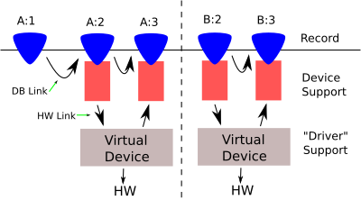
In the database pictured above there are five PVs. Four of the PVs have device support. These four PVs are linked to two separate but identical devices. The fifth PV might be of a record type which does not need device support, or which uses soft device support.
2. Linking Records Together
EPICS database links come in one of two kinds in three classes. The ‘kinds’ are those which link together two records, and those which link a record to hardware. The three classes are: Input, Output, and Forward. Hardware links are either Input or Output links.
More attention is given to the first kind because chaining records together for processing is one of the core EPICS concepts. It is the second however, which we will focus on.
In [ioc_db] an example of linking two records together can be seen between the PVs A:1 and A:2. This could be an input link by A:2 to pull the value of A:1, it could be an output link by A:1 to push a value into A:2, or it could be a forward link by A:1 to A:2.
3. Linking Records To Hardware
Hardware links serve to associate a record’s device support with a particular (virtual) device. In the figure above PV A:2 has an hardware output link, and A:3 has a hardware input link.
Unlike a link between two records, a hardware link is inherently local. Its depends on which physical machine and IOC process it is found in. It is given meaning by the device support, so the same hardware link string will mean two different things when used with two different device supports in the same IOC.
The 9 allowed hardware link types are listed in table [hw_types].
| Type | Field format |
|---|---|
| VME_IO | ‘#Cxx Syy @zzz’ |
| CAMAC_IO | ‘#Bxx Cyy Nzz Att Fuu @vvv’ |
| AB_IO | ‘#Lxx Ayy Czz Stt @uuu’ |
| GPIB_IO | ‘#Lxx Ayy @zzz’ |
| BITBUS_IO | ‘#Lxx Nyy Pzz Stt @uuu’ |
| INST_IO | ‘@xxx’ |
| BBGPIB_IO | ‘#Lxx Byy Gzz @ttt’ |
| RF_IO | ‘#Rxx Myy Dzz Ett’ |
| VXI_IO | ‘#Vxx Cyy Szz @ttt’ |
There are two things to consider with hardware links. How they are implemented, and how they are intended to be used.
A HW link type name is just a label applied to one arm of a C union (defined in link.h). For example, a VME_IO link might be written “#C0x4000 S0x8 @signed”. This is parsed and placed in the appropriate arm of the union; which is itself a C structure with three members: card, signal, and parm. The first two members are short integers and the last is a string. After parsing no further action is taken. This is all that a hardware link is.
This collection of integers and a string is intended to be used as a way of addressing hardware. But since there is so much variation in the way different devices and buses are addressed the implementation must be very generic. The current scheme is a trade off to remove some parsing (ie atoi()) and error checking code which would otherwise be replicated by every device support, and move it into the process database framework.
A link type like VME_IO is so named because it is often convenient to think of addressing a vme card by slot number and a function/channel code, with the string acting as a catch-all for any other information. VME cards do not need to use VME_IO type links and GPIB devices do not need to use GPIB_IO type links. Since VME_IO and GPIB_IO links store the same data (two short ints and a string) they are in fact functionally identical. They differ only in the names used in the two arms of the C union.
4. When a Hardware Link is Not Enough
Hardware links are meant to pass small bits of information to device support. This breaks down when the information to be passed becomes large or when there is initialization to be performed.
It is difficult to handle initialization tasks, which must happen once and only once, in a hardware link which is duplicated in many records. It is tempting to think of giving one record a ‘special’ link which tells device support when to initialize, but there is a better way. Hardware initialization can be done easily and cleanly in the IOC Shell.
A common pattern is for a Device Support to provide an IOC Shell function to accept and preprocess complex hardware addressing. This information is associated with an integer key and stored in a table or linked list. Device support hardware links pass the integer key to the Device Support for each Record, which must individually preform a lookup to retrieve the complete addressing information. This lookup is usually done the Device Support init_record function. An example of this is given below in [ex2].
5. Device Support Private Data
The use of hardware links implies some sort of lookup to get from a set of short integers and a string to a pointer to a memory mapped device, or a system file descriptor/socket for message based devices.
It would be inefficient to do this lookup every time the device must be accessed. For this reason the device support author is provided with the Device Support Private (dpvt) field, which is found in all record types. This field is a void * which may be used to reference any persistent state for individual records. It can not be access via Channel Access.
It could be used to store the cpu address which corrasponds to the base address of a memory mapped device. Most commonly it will store a pointer to a structure defined by the device support author.
6. Driver Support and the Virtual Device
EPICS Driver Support is not a well defined concept. It could be any of the following among others:
-
A set of functions shared between several device supports.
-
Involve IOC Shell functions for setup.
-
An interface to an Operating System driver.
The “official” definition of Driver Support is in terms of the drvet structure defined in drvSup.h. It is a table of function pointers similar to the Device Support dset table.
It provides a way to define another layer of abstraction when it is needed. This could be used to abstract away the differences between varients of a card or even bus access method (VME vs. PCI). The abstract operations presented by this interface to Device Support are essentually a ‘Virtual Device’.
Driver support is not required. In many cases the extra abstraction it provides serve only to add complexity with no real benifit. Knowing when to use it is a skill which develops with time.
The example [ex4] below extends the PRNG device support developed in the Basic EPICS Device Support document to demonstrate a case where Driver Support can be useful.
7. The Full Crate
EPICS is a distributed control system and must be able to scale well, both in number of IOCs as well as the size of any one of these IOCS.
The concepts of Linking exists to enforce isolation between records (and associated Device Supports). The idea is that if records instances can only interact in well understood ways then it is easier to scale to an arbitrarily large number of records. Hardware linking allows this isolation to be broken to the extent necessary to deal the reality with complex devices.
When writing Device Support the author considers a device is layers. For example, first that an ADC card has a channel, then that it has many channels, and finally that it is one cards among many on the bus. It is important to consider that a Device Support will go into an IOC which many have many of its devices, and other devices which it should not interfere with.
Consider what will happen when someone puts 20 identical cards in one VME crate. How will resources be allocated? What base address should each card be assigned? Will all 20 cards interrupt the CPU (at the same time)? These are the types of questions which must be answered to create an IOC which can scale.
8. Example 1
Consider the following a concrete example of the A:* PVs in the database illistrated in figure [ioc_db].
The hardware specific device support is defined in a database definition.
device(ao, GPIB_IO, devAoMine, "My Device")
device(ai, GPIB_IO, devAiMine, "My Device")
The hardware itself is a simple VME card with two registers 0x04 and 0x08. Writing a value to 0x04 causes the value of 0x08 to change. Links of the type GPIB_IO are used to further illustrate that these names mean nothing.
The device support devAoMine takes the sum of the two integer parts of the hardware link and uses this as the VME address of the register it should operate on. The parm string is used to hold optional modifiers.
The record A:1 exists to provide a separate linear scaling for the setting.
The forward link between A:2 and A:3 causes the 0x8 register to be read after the 0x4 register is written.
record(ao,"A:1") {
  field(DTYP, "Soft Channel")
  field(OUT, "A:2")
  field(PINI, "Yes")
  field(UDF, 0)
  field(VAL, 4.2)
  field(CONV, "Linear")
  field(ESLO, -2.0)
  field(EOFF, 1.0)
  field(EGU, "mm")
  field(FLNK, "A:2")
}

record(ao,"A:2") {
  field(DTYP, "My Device")
  field(OUT, "#L0x4000 A0x04 @signed")
  field(FLNK, "A:3")
}

record(ai,"A:3") {
  field(DTYP, "My Device")
  field(OUT, "#L0x4000 A0x08 @signed")
}
9. Example 2
Consider the same device seen above [ex1]. The device support writer makes the decision to create an IOC Shell function called initMyDev(int,int,string) and adds it to the IOC start script.
dbLoadDatabase("dbd/mydevioc.dbd")
mydevioc_registerRecordDeviceDriver(pdbase)

initMyDev(0,0x4000,"signed")

dbLoadRecords("db/mydev.db","prefix=A:,card=0")

iocInit()
This associates the VME card with the A16 base address 0x4000 with the integer key 0, which is passed as $(card) when the records are loaded.
The database then becomes the following:
record(ao,"$(prefix)1") {
  field(DTYP, "Soft Channel")
  field(OUT, "A:2")
  field(PINI, "Yes")
  field(UDF, 0)
  field(VAL, 4.2)
  field(CONV, "Linear")
  field(ESLO, -2.0)
  field(EOFF, 1.0)
  field(EGU, "mm")
  field(FLNK, "A:2")
}

record(ao,"$(prefix)2") {
  field(DTYP, "My Device")
  field(OUT, "#L$(card) A0x04 @")
  field(FLNK, "A:3")
}

record(ai,"$(prefix)3") {
  field(DTYP, "My Device")
  field(OUT, "#L$(card) A0x08 @")
}
It this simple example we do not gain much for the trouble, but this approach is flexible in a way that hardware links alone are not.
10. Example 3
Let us expand on the previous example by adding four more cards. The only change required is in the IOC start script.
dbLoadDatabase("dbd/mydevioc.dbd")
mydevioc_registerRecordDeviceDriver(pdbase)

initMyDev(0,0x4000,"signed")
initMyDev(1,0x5000,"signed")
initMyDev(2,0x6000,"signed")
initMyDev(3,0x7000,"signed")
initMyDev(4,0x8000,"signed")

dbLoadRecords("db/mydev.db","prefix=A:,card=0")
dbLoadRecords("db/mydev.db","prefix=B:,card=1")
dbLoadRecords("db/mydev.db","prefix=C:,card=2")
dbLoadRecords("db/mydev.db","prefix=D:,card=3")
dbLoadRecords("db/mydev.db","prefix=E:,card=4")

iocInit()
This will create five copies of the PVs defined in db/mydev.db, each with a different prefix communicating with a different card. The fact that this can be done without modifying (or even recompiling) any of the Device Support code is what allows an EPICS IOC to quickly and easily scale to large numbers of devices.
11. Example 4 (Full)
Now for a full example of the topics discussed in this document. The device support for the pseudo-random number generator developed in the Basic EPICS Device Support document can be extended to make use of Driver Support. The drivers in this case will be used to select between two possible random number distributions.
11.1. Global Definitions
We begin by defining the Driver Support interface. This is the ‘Virtual Device’ that our Device Support will use. In this case we have only two operations: create and read. The create operation refers to creating a ‘Virtual Device’, and could also be named find.
The ‘hardware address’ in this example is the seed value for the pseudo random number generator. The void* returned by the create function must be used when the read function is called, and allowing the driver to hide its state. This pointer is effectively the this pointer of C++.
The following code should be placed in the file prngApp/src/drvprngdist.h.
typedef void* (*create_prng_fun)(unsigned int seed);

typedef int (*read_prng_fun)(void* tok);

struct drvPrngDist {
  drvet base;
  create_prng_fun create_prng;
  read_prng_fun read_prng;
};
This definition must be shared between the Driver Support code and the Device Support(s) which will use it.
Now we define an additional structure which can be though of as the public data members of the drvPrngDist class.
struct instancePrng {
  ELLNODE node; /* must be first */
  struct drvPrngDist* table;
  void* token;
  int id;
};
A ELLNODE is also included as a convinience for the lookupPrng function; which will be used by Device Support to locate a specific instance of drvPrngDist based on the id number passed to it in a hardware link.
struct instancePrng* lookupPrng(short N);
11.2. DBD
At this point we should create the database definition as prngApp/src/prngdist.dbd.
device(ai, VME_IO, devAiPrngDist, "Random Distribution")
driver(drvPrngUniform)
driver(drvPrngGaussian)
registrar(prngDist)
11.3. IOC Shell Functions
Creating instance of PRNG ‘Virtual Devices’ will be accomplished with an IOC Shell function called createPrng in the file prngApp/iocshdist.c.
static ELLLIST devices={{NULL,NULL},0};

static const char dpref[]="drvPrng";
Here we define a list which will hold all created device instances and the prefix for Driver Support names (as seen in the dbd).
void
createPrng(int id,int seed,const char* dist)
{
  unsigned int s=(unsigned int)seed;
  char* dname=NULL;
  size_t dlen;
  struct instancePrng* inst=malloc(sizeof(struct instancePrng));

  if(!inst){
    epicsPrintf("Out of Memory\n");
    goto error;
  }

  /* sizeof(dpreg)==strlen(dpref)+1 */
  dlen=sizeof(dpref)+strlen(dist);

  dname=malloc(dlen);
  if(!dname){
    epicsPrintf("Out of Memory\n");
    goto error;
  }

  strcpy(dname,dpref);
  strcat(dname,dist);
Some boiler plate for allocation and construction of the Driver Support name string.
  inst->table=(struct drvPrngDist*)registryDriverSupportFind(dname);
  if(!inst->table){
    epicsPrintf("Unknown Distribution type\n");
    goto error;
  }
When a Driver Support is registered with a running IOC its name is placed in a list which can be queried with the registryDriverSupportFind function. In this way the dist argument is used to select which Driver Support is to be used.
Since the two Driver Supports are called drvPrngUniform and drvPrngGaussian the two valid values for the dist argument are ‘Uniform’ and ‘Gaussian’.
  inst->token=inst->table->create_prng(s);
  if(!inst->token){
    epicsPrintf("Failed to create PRNG.\n");
    goto error;
  }
The Driver Support create function is used to create a new instance token.
  inst->id=id;
  ellAdd(&devices,&inst->node);

  return;

error:
  free(dname);
  free(inst);
  return;
}
All that remains is to add the instance to the devices list so the lookup function can find it.
The lookup function is short and fairly simple. It iterates through the list of instances until it finds a match.
struct instancePrng* lookupPrng(short N)
{
  ELLNODE* node;
  struct instancePrng* ent;

  for(node=ellFirst(&devices); node; node=ellNext(node)){
    ent=(struct instancePrng*)node; /* Use CONTAINER() in 3.14.11 */
    if(ent->id==N)
      return ent;
  }

  return NULL;
}
11.4. Device Support
Now we turn to the Device Support functions for the AI record type (prngApp/src/devprngdist.c). In this case the init_record and read_ai functions become thin wrappers for the Driver Support functions. Normally this would be a sign that the task is too simple to benifit from Driver Support and suggests that we instead create two different Device Supports.
static long init_record(aiRecord *pao)
{
  struct instancePrng* priv;

  priv=lookupPrng(pao->inp.value.vmeio.card);
  if(!priv){
    recGblRecordError(S_dev_noDevice, (void*)pao,
      "Not a valid device id code");
    return S_dev_noDevice;
  }

  pao->dpvt=priv;

  return 0;
}
Here we use the lookupPrng function with (part of) the hardware link. Only the card value is used because nothing more is needed.
If found the instance is stored in the Device Support Private field for future use.
static long read_ai(aiRecord *pao)
{
  struct instancePrng* priv=pao->dpvt;

  pao->rval=priv->table->read_prng(priv->token);

  return 0;
}
To read a random number we use the read function in the function table stored with the instance and pass it the instance token which was created with the create function also in this table.
11.5. Driver Support (Uniform)
We will define two seperate drivers. The first will generate random numbers in a uniform distribution (prngApp/src/drvprngunif.c).
struct uniform {
  unsigned int state;
};
First we define a structure which stores the state for the generator. This is effectively the private data of the drvPrngDist class. A pointer to this structure will act as the instance ‘token’.
static
void* create(unsigned int seed)
{
  struct uniform* priv=malloc(sizeof(struct uniform));

  if(!priv)
    return NULL;

  priv->state=seed;

  return priv;
}

static
int read(void* tok)
{
  struct uniform* priv=tok;

  return rand_r(&priv->state);
}

static
struct drvPrngDist drvPrngUniform = {
  { 4,
    NULL,
    NULL,
  },
  create,
  read,
};
epicsExportAddress(drvet,drvPrngUniform);
The actual definition of this Driver Support is straight forward.
11.6. Driver Support (Gaussian)
While the difference between the Gaussian and Uniform generators is small they are placed in separate files to demonstrate that the two Driver Supports can be completely isolated from each other.
struct gaussian {
  unsigned int state;
};

static
void* create(unsigned int seed)
{
  struct gaussian* priv=malloc(sizeof(struct gaussian));

  if(!priv)
    return NULL;

  priv->state=seed;

  return priv;
}

static
int read(void* tok)
{
  struct gaussian* priv=tok;
  int ret=0, i=8;

  while(i--)
    ret+=rand_r(&priv->state)/8;

  return ret;
}
To approximate a Gaussian distribution, several uniform random numbers are summed in accordance with the Central Limit Theorem.
static
struct drvPrngDist drvPrngGaussian = {
  { 4,
    NULL,
    NULL,
  },
  create,
  read,
};
epicsExportAddress(drvet,drvPrngGaussian);